
Address
6. October, Cairo, Egypt

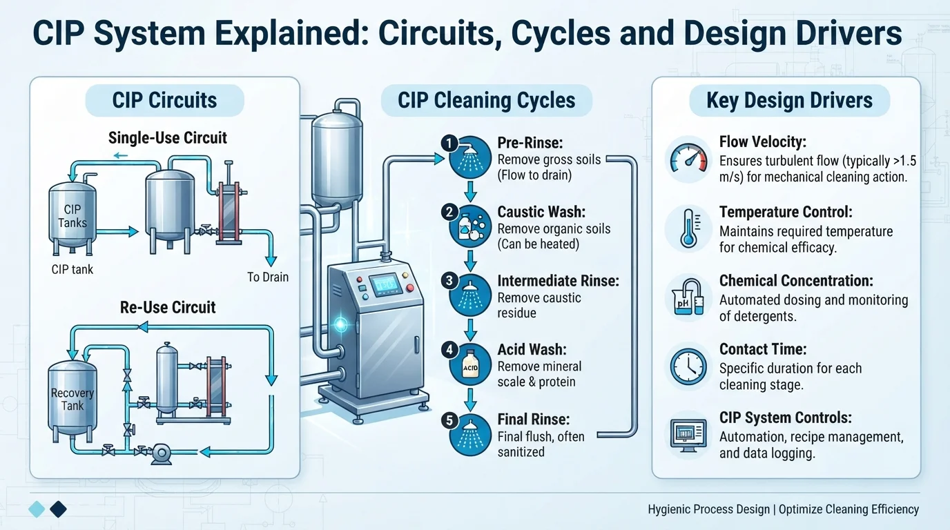

Nobody in a food plant wants to dismantle a pipe network every night to clean it. A CIP system exists so they do not have to. Cleaning in place pushes water, detergent and sometimes disinfectant through tanks, pipes, pumps and heat exchangers while everything stays where it is installed. It sounds simple, and at the level of a diagram it is. The difficulty is in the details: what makes a CIP system clean reliably, why one design suits a dairy and another a juice line, and what decisions at the design stage decide how it behaves for years to come.
This guide explains how a CIP system works: the basic principle, the stages of a typical cycle, how circuits are defined, and the design drivers that shape the equipment. It is written for plant managers, project engineers and owners who need to understand the system well enough to specify it, compare offers and ask the right questions.
What a CIP System Actually Does?
Clean-in-place is an automated method of cleaning the interior surfaces of process equipment without taking it apart. As the Wikipedia article on clean-in-place summarises, it relies on turbulent flow through piping and spray devices in tanks and vessels, and removes residue through a combination of heat, chemical action and flow. A CIP system is the set of tanks, pumps, valves, heat exchangers, sensors and controls that delivers those cleaning fluids to the plant and returns them.
It does two jobs at once. It removes product residue, which can feed microbial growth and cause cross-contamination, and it prepares surfaces so that the next production run starts clean. Whether a particular CIP system is “good” is therefore not a question about the unit alone. It depends on whether the plant it serves has been designed to be cleanable, which is why hygienic design and the CIP system have to be developed together.
The Four Variables Behind Every CIP System
Cleaning scientists describe the process with a simple model, often called the Sinner circle or TACT: time, action, chemistry and temperature. An Alfa Laval CIP presentation explains the principle plainly: the four elements together accomplish the cleaning task, and a larger share of one allows a smaller share of the others. More heat can allow less time; more mechanical action can allow lower temperature or less chemical.
For the buyer, this has a practical meaning. When a supplier proposes a CIP system, ask which variables the design relies on and what happens if one drifts. A circuit with marginal flow cannot be rescued by adding chemical. A cycle that runs cold will take longer or need stronger detergent. Each of the four needs to be designed, controlled and measured. The commonly cited requirement for flow in pipework is a minimum velocity of around 1.5 metres per second, according to several industry sources, though the right figure for your plant should come from your supplier’s design and your quality standards.
The Stages of a Typical CIP Cycle
A CIP system runs a sequence of stages, and the details vary with product, soil and plant. A commonly described sequence has five steps, as set out in a glossary entry on clean-in-place: pre-rinse, caustic wash, intermediate rinse, acid wash and final rinse. Some plants add a sanitising or disinfection step.
The pre-rinse flushes away loose product with water and sends it to drain or recovery. The caustic wash, using an alkaline detergent, removes fats, proteins and organic soil. An intermediate rinse clears the caustic before the next step, preventing the alkaline and acid solutions from mixing. The acid wash removes mineral deposits that alkaline cleaning leaves behind, which matters particularly where milk or hard water forms scale. The final rinse removes chemical residues so the plant is ready for production, and a disinfection step, using heat or a chemical, may follow.
Not every plant needs every stage. A juice line with light soiling and a dairy line with proteins and minerals will not run identical programmes. The CIP system design should accommodate the programmes the plant needs, with enough flexibility to adjust them as products change. Our CIP systems page explains how this scope is organised in an engineering project.
How a CIP System Is Organised: Circuits?
A plant is not cleaned all at once. It is divided into circuits, each a closed loop that the CIP system can supply and return. A circuit might include a group of tanks, a run of product pipework with its pumps and valves, a heat exchanger, or a filling machine. Splitting the plant this way keeps flow rates manageable, allows production to continue in one area while another is cleaned, and prevents cleaning fluid from entering lines in production.
Circuits matter because a CIP system can only clean what it can reach. Every surface needs a defined flow path from supply to return, with no dead legs, no branches that stagnate and no components that block flow. That is where piping layout, valve arrangements and tank design intersect with the CIP design, a point we develop in our comparison of sanitary process piping and utility piping. For tanks, cleaning uses spray devices rather than pipe-style flow, which need different flow rates from line circuits. Our stainless steel tanks page covers the tank side of that interface.
The Main Components of a CIP System
Although layouts differ, most plants build a CIP system from the same set of parts. Tanks hold the water, caustic and acid solutions, sometimes with a recovery tank for reusing rinse water or chemical. A supply pump delivers the solution to the circuit at the required flow, and a return line or return pump brings it back. A heat exchanger or steam injection brings the solution to temperature. Dosing equipment adds concentrated chemical. Valves, often arranged in valve clusters or arrays, direct fluids to the chosen circuit and keep cleaning fluid separate from production lines. Instruments measure temperature, flow, conductivity and sometimes turbidity, and a controller runs the programmes.
A good CIP system pays attention to the return as much as the supply. Measuring concentration and temperature on the return line shows what the cleaning fluid is doing at the far end of the circuit, which is where problems appear first.
Design Drivers: What Shapes a CIP System
Several decisions determine the final design of a CIP system, and they are best discussed before any equipment is ordered.
Soil and product. Milk proteins, fruit pulp, tomato solids and fats behave differently, and each needs a suitable programme. The product range sets the stages, the chemistry and the temperature.
Circuit layout. The number, size and arrangement of circuits determine pump capacity, tank volumes and valve count. Large circuits with mixed diameters make it hard to achieve the same flow everywhere.
Flow and pump sizing. Reaching adequate turbulence in pipework and adequate coverage in tanks is the core hydraulic task. Spray devices and line circuits can need different flow rates, so one pump setting rarely suits both without design attention.
Temperature and utilities. A CIP system draws hot water, steam, chemicals and power. Its demand has to be included in the plant’s utility schedule, not added afterwards, which links this topic to our guide to industrial utilities.
Recovery and consumption. Reusing rinse water or chemical can reduce consumption, at the price of extra tanks, controls and care to avoid carry-over. The right balance depends on cost, volumes and hygiene priorities.
Automation and verification. Programmes, interlocks, data logging and alarms belong in the design, not just the commissioning checklist. Our industrial automation and control page describes how control scope is typically organised.
Hygienic design of the CIP installation itself. EHEDG’s GL 50 on hygienic design requirements for CIP installations addresses user requirement specifications and validation of CIP installations. These guidelines are best practice rather than law, so decide with your quality team which ones your plant will follow.
Central or Decentralised: A Brief Note
Some plants serve every circuit from a single central CIP system; others use smaller units close to the areas they clean. The choice affects pipe lengths, flexibility, capital cost and how cleaning schedules overlap. It deserves its own discussion, but it is worth knowing at this stage that the layout of the CIP system is a decision, not a given.
Commissioning, Validation and Ongoing Performance
A CIP system is only as good as its proven performance. Commissioning should confirm that each circuit achieves the designed flow, that temperature and concentration reach and hold their set values, that the programmes run correctly, and that the final rinse leaves no residue. Many plants also verify cleaning with swabs or other checks as part of their own quality systems. The critical parameters must remain within specification for the duration of the cycle; if they do not, as the Wikipedia article notes, cleaning cannot be assured and the cycle has to be repeated. Our commissioning page describes how this stage is organised.
Performance also needs maintaining. Sensors drift, spray devices clog, gaskets wear and chemical supplies change. A plan for calibration, inspection and periodic review keeps a CIP system doing what it was designed to do.
An Illustrative Scenario
Consider a hypothetical plant that has added a new tank to an existing line. The tank is connected to the existing CIP system, and the cycle runs to completion every night. After a few weeks, an inspection shows residue inside the new tank near the top. The cause is not chemistry or time. The spray device installed in the new tank needs a higher flow than the circuit delivers, because the pump was sized for the old tank and the circuit now serves both. The remedy is hydraulic: adjust the circuit, change the spray device or add capacity. The lesson is that a CIP system has to be reviewed whenever the plant it serves changes.
Common Mistakes With CIP Systems
Several errors recur. Designing the process line first and the CIP system afterwards, leaving no flow path for cleaning. Sizing pumps from nominal pipe diameter without checking real circuits. Ignoring dead legs. Combining tanks and long pipe runs in one circuit without considering their different flow needs. Omitting return measurements. And treating the CIP system as a purchased unit rather than an engineered interface between the cleaning plant and the process plant.
Five Questions to Ask Before You Specify
Before approving a design, ask:
- Which circuits does the CIP system serve, and what flow does each need?
- Which cleaning programmes are required for each product and soil?
- How do utilities, chemicals and drains support the cycles?
- How will temperature, concentration and flow be measured and verified?
- What happens to the design when the line is changed or extended?
FAQ: How a CIP System Works
What is a CIP system?
A CIP system is an automated cleaning installation that circulates water, detergent and sometimes disinfectant through process equipment without dismantling it, using controlled flow, temperature, chemical concentration and time.
What are the stages of a CIP cycle?
A commonly described sequence is pre-rinse, caustic wash, intermediate rinse, acid wash and final rinse, with an optional sanitising step. Actual programmes depend on the product and the plant.
Does a CIP system clean tanks and pipes the same way?
Not exactly. Pipework relies on flow through the line, while tanks usually use spray devices. Their flow requirements differ, which is one reason a CIP system is organised in circuits.
Is a CIP system the same as sterilisation?
No. Cleaning removes soil; disinfection or sterilisation reduces or eliminates microorganisms. Some CIP system programmes include a disinfection stage, but that is a separate purpose.
Plan Your CIP System With the Process
A CIP system works best when it is designed together with the plant it serves. If you are planning a new line, an expansion or a cleaning upgrade and want to discuss circuits, cycles and utilities with an engineering team, read about our CIP systems scope or contact our engineering team to talk through your project.